Zylo Solar Zylo Solar

2026 Top How to Connect Solar Panels in Series vs Parallel?

Time:2026-09-28 Author:Aria
0%

Choosing a solar-panel wiring layout affects system voltage, current, performance, and equipment compatibility. How to connect solar panels in series vs parallel is not just a question of joining positive and negative leads. It starts with the ratings of your panels, charge controller, inverter, and wiring. The difference matters.

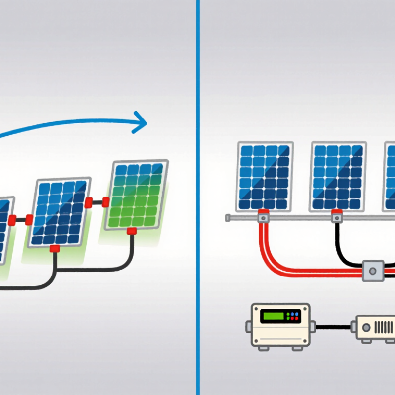
In a series connection, one panel’s positive lead connects to the next panel’s negative lead. The voltages add, while current generally remains close to that of one panel. In parallel, matching positive leads and negative leads join; current adds, while voltage stays near the level of one panel. These are useful basics, not a complete design.

Shade changes things. A shadow across one panel in a series string may reduce the output of that string, depending on the modules and system components. Parallel wiring can limit some shading effects, but it may require thicker conductors or suitable combining equipment. Small details count. Cable length, connector type, overcurrent protection, and the controller’s maximum input ratings all deserve attention.

This guide explains how each arrangement works, what trade-offs to expect, and which system details to check before installation. Compare the panel labels with the equipment manuals, and follow the manufacturers’ wiring diagrams. If specifications are unclear, pause and ask a qualified solar professional. A neat-looking connection is not proof of a safe one. I’ve seen people focus on the wiring diagram and overlook the controller limit; that’s an easy mistake, and worth checking twice.
2026 Top How to Connect Solar Panels in Series vs Parallel?

How Solar Panel Series and Parallel Connections Work

Connecting solar panels in series means joining the positive lead of one panel to the negative lead of the next. Their voltages add, while the current stays close to that of one panel. This can suit systems with longer cable runs, but the combined voltage must remain within the charge controller or inverter’s limits. Cold weather can raise panel voltage, so check the equipment specifications rather than relying only on the rated figures.

In a parallel connection, positive leads join positive leads, and negative leads join negative leads. Voltage stays near the level of one panel, while current increases. This can help when the system needs more current at a lower voltage. More current may require thicker cable, and the design may call for string fuses or other protective equipment. The wiring diagram can look simple on paper. Real cable lengths and panel ratings matter.

Panels connected in the same string should have compatible electrical characteristics. A shaded panel in a series string can reduce output across that string; parallel layouts may limit that effect, though they do not remove every shading problem. It is easy to assume parallel is always safer or series is always more efficient. Neither is true in every setup. Check the panel’s open-circuit voltage, current ratings, and controller limits before choosing a layout. If those figures are unclear, ask a qualified solar professional to review the plan.

Check Panel Ratings, System Voltage, and Inverter Compatibility

Series wiring raises voltage while current stays nearly constant; parallel wiring raises current while voltage stays similar. Check each module’s Voc, Vmp, Isc, and Imp against the inverter’s operating range and absolute input limits. Cold weather can push open-circuit voltage above its nameplate value, so apply the module’s temperature coefficient using the site’s lowest design temperature. In heat, operating voltage can fall. Small details matter.

The U.S. National Renewable Energy Laboratory’s 2024 Annual Technology Baseline uses a utility-scale DC-to-AC inverter loading ratio near 1.34 as a reference assumption. That is not a residential stringing target; it illustrates why panel capacity and inverter limits must be assessed together. For a real array, calculate the series-string cold Voc and hot Vmp, then check that parallel-string current remains within the inverter’s input limit. Confirm the permitted number of strings and any per-input current cap in the inverter documentation. I still recheck these figures by hand, because a neat-looking string count can hide a voltage mismatch. If the ratings or site temperatures are uncertain, have a qualified solar professional verify the design before installation.

Connect Solar Panels in Series Step by Step

Connecting solar panels in series is a practical way to raise string voltage while keeping current near that of one panel.

53% SEIA and Wood Mackenzie’s 2024 U.S. Solar Market Insight reported that solar supplied 53% of new U.S. electricity-generating capacity added in 2023. More installations make careful wiring checks increasingly important.

Keep it simple.

Start with the equipment manuals. Confirm that the panels have compatible electrical ratings and that the combined string voltage stays below the charge controller or inverter limit. Include the higher voltage panels can produce in cold weather.

Switch off and isolate the system before handling connectors; sunlight can still make panels live. If the design is unclear, ask a qualified solar electrician.

Lay out the panels and identify each positive and negative lead. Connect one panel’s positive lead to the next panel’s negative lead, using only compatible, weather-rated connectors. Repeat for each panel in the string.

The two unused end leads become the string output: one positive, one negative. Check polarity and connector seating before connecting them to the controller or inverter.

This step is easy to rush, and that is exactly when polarity gets missed. Have a qualified person verify the design and measurements before energizing the system.

Connect Solar Panels in Parallel Step by Step

Connect Solar Panels in Parallel Step by Step

In a parallel array, connect every positive lead together and every negative lead together, using compatible branch connectors or a properly rated combiner. Voltage stays close to one panel’s operating voltage, while current adds. For example, two panels producing 10 amps each can deliver about 20 amps under matching conditions. Check the label. Confirm that the charge controller or inverter accepts the combined current and array voltage before wiring.

Work with the array isolated from the controller, and remember that illuminated panels can still produce hazardous DC voltage. Check polarity with a meter, inspect connectors for damage, and follow the equipment manufacturer’s wiring diagram. Secure connections against moisture and strain; never separate connectors while current is flowing. Mismatched panels, orientations, or shading can reduce output, so parallel wiring is not automatically the best choice for every roof.

NREL’s review, Photovoltaic Degradation Rates—An Analytical Review (2013), examined nearly 2,000 reported rates and found a median degradation rate of about 0.5% per year. That long service life makes careful connections worthwhile, though the statistic does not predict an individual system’s performance. I still double-check the controller’s current limit; it is an easy detail to overlook when adding panels.

2026 Top How to Connect Solar Panels in Series vs Parallel? - Connect Solar Panels in Parallel Step by Step
Comparison Dimension Series Connection Parallel Connection Practical Guidance
How panels are connected Connect the positive terminal of one panel to the negative terminal of the next. The two free terminals connect to the system. Connect all positive terminals together and all negative terminals together using appropriately rated branch connectors or a combiner. Follow the panel and equipment manufacturers’ wiring diagrams. Confirm polarity before making connections.
Voltage and current Panel voltages add; string current is approximately the current of one panel. Panel currents add; array voltage is approximately the voltage of one panel. Use the same measurement basis when comparing panels, such as maximum-power voltage (Vmp) and current (Imp).
Illustrative two-panel example For two identical panels, each rated at Vmp 31.0 V and Imp 12.9 A: approximately 62.0 V and 12.9 A at maximum power. For the same two panels: approximately 31.0 V and 25.8 A at maximum power. Illustration only: actual operating values vary with sunlight, temperature, and panel specifications.
Open-circuit voltage and short-circuit current example With each example panel rated Voc 37.0 V and Isc 13.5 A: approximately 74.0 V Voc and 13.5 A Isc. With the same example panels: approximately 37.0 V Voc and 27.0 A Isc. Check corrected cold-weather Voc against the controller or inverter’s maximum DC input voltage. Check current limits and required protection devices.
When it may be suitable Often used when the charge controller or inverter needs a higher input voltage and the combined string voltage remains within equipment limits. Often used when a lower array voltage is appropriate and the controller or inverter can accept the combined current. Choose a configuration only after checking the complete system’s voltage, current, and power ratings.
Partial shading and mismatch Shading or mismatch on a panel can reduce string output; panel bypass diodes may limit some effects but do not eliminate them. Branches operate in parallel, but shading or mismatch can still reduce array output and affect operating conditions. Use panels with compatible electrical characteristics. Avoid mixing different panel types in the same string unless the equipment design permits it.
Connect Solar Panels in Parallel: Step by Step
1Check ratings Read each panel’s label or datasheet for Voc, Isc, Vmp, Imp, and maximum series-fuse rating. Confirm that the panels are compatible for parallel connection. Verify that the controller or inverter supports the array voltage and the combined current, including applicable design margins.
2Make the system safe Follow the equipment instructions to isolate the controller or inverter and open the appropriate DC disconnects before wiring. Cover panels or work in low-light conditions when appropriate. Solar panels can produce hazardous DC voltage in daylight. Use suitable tools and protective equipment; consult a qualified installer if unsure.
3Prepare rated components Use conductors, connectors, branch connectors, and any combiner equipment rated for the expected DC voltage, current, outdoor exposure, and installation conditions. Do not connect incompatible connector types or exceed a connector’s or cable’s ratings.
4Join positive leads Connect each panel’s positive lead to the positive branch input or positive bus using correctly rated equipment. Keep connections dry, clean, fully seated, and protected from strain or damage.
5Join negative leads Connect each panel’s negative lead to the negative branch input or negative bus. Check polarity with a suitable meter before connecting the combined array to the controller or inverter.
6Check protection requirements Determine whether string fuses or breakers are required from the panel specifications, number of parallel strings, equipment instructions, and applicable electrical code. Use correctly rated DC overcurrent protection and disconnects where required. Do not assume protection is unnecessary for every parallel array.
7Connect and verify With the system isolated, connect the combined positive and negative array conductors to the designated PV input according to the equipment manual. Recheck polarity and secure all connections. Restore operation in the sequence specified by the controller or inverter manufacturer, then confirm that readings are within equipment limits.
Important safety reminder Never exceed the equipment’s maximum PV input voltage or current. Follow local electrical codes and product instructions; have a qualified solar electrician review installations that involve unfamiliar equipment or high DC voltages.

Compare Both Wiring Methods and Verify the Finished Array

Series wiring adds panel voltage while keeping string current nearly constant; parallel wiring keeps voltage steady and adds current. Series strings can suit higher-voltage inputs, but shade on one panel may reduce string output. Parallel branches can limit that effect, yet higher current demands correctly sized conductors and overcurrent protection. Check the inverter’s voltage and current limits before choosing either layout. Small details matter.

The IEA PVPS Snapshot of Global PV Markets 2024 estimates 407–446 GW of new photovoltaic capacity was installed worldwide in 2023. That scale makes careful commissioning important, not optional. After wiring, compare each string’s measured open-circuit voltage with its temperature-adjusted design value. Confirm polarity, inspect connectors for full engagement, and check that parallel strings have compatible voltages. A clamp meter can help verify operating current without disconnecting conductors. Real roofs are less tidy than diagrams; shade, long cable runs, and loose connections can explain unexpected readings.

Tip: Record string voltage and operating current under steady sunlight, then compare them with design calculations and inverter limits. Use properly rated instruments, follow equipment instructions, and have a qualified solar professional perform live electrical tests. If readings differ, pause and investigate before energizing the system.

Solar Panels in Series vs. Parallel: Voltage and Current

Illustrative comparison for two identical 400 W modules, each with a maximum-power voltage (Vmp) of 33 V and maximum-power current (Imp) of 12.1 A.

How to read it: In series, module voltages add while current stays about the same. In parallel, currents add while voltage stays about the same. Both arrangements produce approximately 800 W under ideal conditions. Before connecting or commissioning an array, check module nameplate values, equipment limits, polarity, and wiring against the manufacturer’s instructions; shading and real-world conditions can change output.

FAQS

What happens when solar panels are connected in series?

Their voltages add, while current stays close to one panel’s current. Check the controller or inverter voltage limit, especially in cold weather.

What happens when panels are connected in parallel?

Voltage stays near one panel’s level, while current increases. Two matching panels producing 10 amps each may provide about 20 amps.

How do I choose between series and parallel wiring?

Compare panel ratings with the inverter or controller limits. Series can suit higher-voltage inputs; parallel can provide more current at lower voltage. Neither layout always works best.

Can shade affect panels connected in series?

Yes. A shaded panel can reduce output across its string. Parallel wiring may limit this effect, but it does not eliminate shading losses.

What should I check before wiring panels in parallel?

Check polarity, panel compatibility, combined current, and equipment limits. Higher current may require thicker conductors and suitable overcurrent protection. Small details matter.

Is it safe to disconnect solar connectors while current is flowing?

No. Isolate the array before working, and never separate connectors under load. Sunlit panels can still produce hazardous DC voltage.

How can I check a finished solar array?

Verify polarity and connector engagement. Compare measured string voltage with the temperature-adjusted design value. A clamp meter can check operating current without disconnecting conductors.

What should I do if readings do not match the design?

Pause before energizing the system. Check for shade, loose connections, long cable runs, or incompatible strings. I still double-check current limits; that detail is easy to miss.

Conclusion

How to connect solar panels in series vs parallel depends on the electrical needs of your system. In a series connection, the positive lead of one panel connects to the negative lead of the next, increasing the array’s voltage while keeping current similar to that of one panel. In a parallel connection, positive leads join positive leads and negative leads join negative leads, increasing current while keeping voltage similar. Before choosing either method, check each panel’s ratings, the system’s voltage limits, and whether the inverter or charge controller can handle the resulting electrical values.

For a series array, connect panels in sequence and route the two unused end leads to the system input. For a parallel array, use appropriately rated connectors or a combiner to join matching leads before connecting them to the system. Follow the equipment instructions, use suitable wiring and protection, and verify polarity and connections before operation. Comparing voltage, current, shading conditions, and equipment limits helps determine which arrangement is appropriate and confirms the finished array is connected correctly.

Aria

Aria

Aria is a dedicated marketing professional with a deep passion for innovative strategies and a keen understanding of our company's product offerings. With a wealth of experience in the industry, Aria excels at crafting engaging content that highlights the unique features and benefits of our......